When designing for low-speed signals, engineers are most concerned with how the signal gets from its source to its destination. When signals reach the hundreds of MHz or Ghz level, their concern changes. At such high frequencies, engineers need to worry about whether or not the signal will reflect back onto the alignment.
Key points of this article:
- Understand what RF reflection is.
- Impact of RF reflection on signal integrity.
- The way to suppress RF reflections.
What is RF reflection?
When designing for low-speed signals, engineers are most concerned with how the signal gets from its source to its destination. When signals reach the hundreds of MHz or Ghz level, their concern changes. At such high frequencies, engineers need to worry about whether or not the signal will reflect back onto the alignment.
RF reflection is similar to a sound wave bouncing back and creating an echo. The impact and bounce of water waves is similar. Reflection occurs when a wave encounters a discontinuity in the medium in which it travels, and the same principle applies to RF-reflected waves.
RF reflections must be taken into account when designing transmission lines. One of the basic principles of transmission line design is to ensure that the characteristic impedances of the driver, the trace, and the load are matched. Characteristic impedance is not defined by resistance or the length of the trace, but by the dielectric, the width of the trace, and the spacing between the trace and the plane.
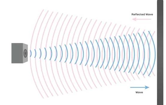
RF reflection is similar in principle to acoustic wave reflection and occurs when the characteristic impedance is discontinuous.
In order to ensure that the driver fully transmits the RF signal to the load, the characteristic impedances on the transmission line must be equal and matched. Any discontinuity in the impedance will cause the RF wave to bounce back to the driver. This is known as RF reflection.
How does RF reflection affect signal integrity?
Whenever there is a mismatch in the characteristic impedance, the signal will reflect. However, at low signal speeds, this hardly causes a substantial problem. When the length of the traces or conductors is equal to or greater than 1/4 of the signal wavelength, RF reflections can be detrimental.
In other words, RF reflection is a concern at GHz frequencies. When a signal reflects due to impedance discontinuities, two things happen:
signal attenuation
The signal is attenuated because not all of the energy is transmitted to the load side. This affects the quality of the transmission and the receiver may need an amplifier to receive the signal.
signal interference
Reflections cause the signal to bounce back and interfere with the incident wave from the source. This collision causes interference and results in waveform peaks at certain points, known as "incident wave" points.
The amplitude of certain peaks may exceed the tolerance limits of some components, resulting in component damage. In less severe cases, signal integrity is adversely affected when reflected waves interfere with the signal being transmitted.
RF reflection prevention through impedance matching
Preventing RF reflections is not an easy task. There are many factors that determine the continuity of the characteristic impedance of a transmission line. The dielectric constant of the substrate, the width and thickness of the alignment all affect the characteristic impedance of the transmission line. The key is to get the ideal parameter values.
Other impedance matching methods can be used in the design. For sources with low output impedance, series termination matching will be helpful, where a terminating resistor is placed between the source and the transmission line. Also, use parallel termination matching to match a signal source with very low impedance to a load end with higher impedance.
